Phased Array Sonar
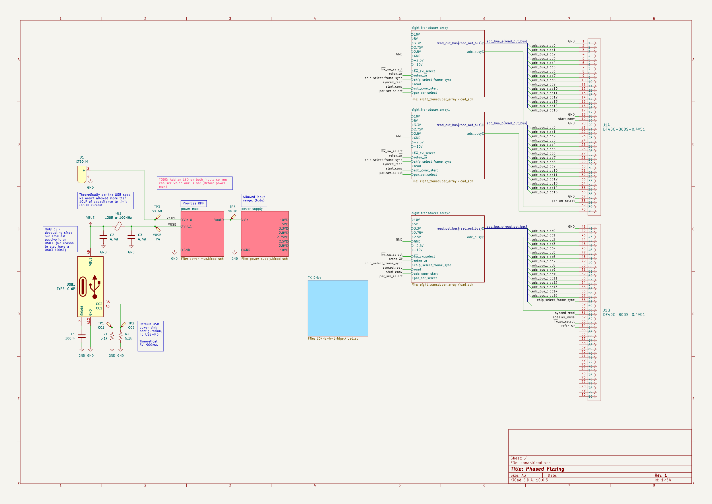
Top-level schematic of the first version of the board
Overview
Josh Himmens and I are designing a sonar that uses a grid of microphones to find both how far away something is and which direction it's in. A speaker sends out a short chirp, and since the echo reaches each microphone at a slightly different time, we can work out where it came from.
The project is still in design, and none of it has been tested on real hardware yet.
Josh designed the receive side and has led the redesign since. I was in charge of power for the first version of the board. My main contributions were:
- Designing the power supply converters
- A power mux so the board can run from either USB-C or a battery
- Starting the transmit driver
- Setting up our shared KiCad part library and merging our repos into one
Architecture
The first version had 24 analog microphones split into three groups of eight. Each microphone had its own amplifier and filter, and each group went to its own 8-channel ADC. All three ADCs start sampling on the same signal so every microphone gets measured at the same instant, which matters because the direction of an echo comes from the timing differences between microphones.
Between the ADCs, amplifiers, microphones, and transmitter, that design needed a LOT of different supply voltages, including +10 V and -10 V for the ADCs.
Since then, Josh has redesigned the receive side around digital microphones that connect straight to an FPGA. That removes the ADCs, the amplifiers, and most of the power supplies, which makes the board a lot easier to get right with the time we have, at the cost of a bit more noise. The FPGA sends the raw microphone data to a laptop over USB, and all of the signal processing happens in Python on the laptop because changing Python is much faster than changing FPGA code.
The new layout is a 5x5 grid of microphones with the middle spot left for the transmitter. The transmitter plugs in through a connector, so we can try different ones without making a new board.
Implementation
Power
The board can run from USB-C or from an XT60 connector for a battery or bench supply. USB-C without USB-PD only gives us 5 V at 900 mA, which isn't enough for the transmitter, so the XT60 is there for anything that needs more.
The two inputs are combined with ideal diodes, which act like normal diodes but with a much smaller voltage drop. Whichever input is higher powers the board, neither input can feed back into the other, and the board is protected if a supply gets plugged in backwards.
The USB spec only allows 10 µF of capacitance on the USB power line to limit inrush current, so I kept the capacitance on the USB input under that.
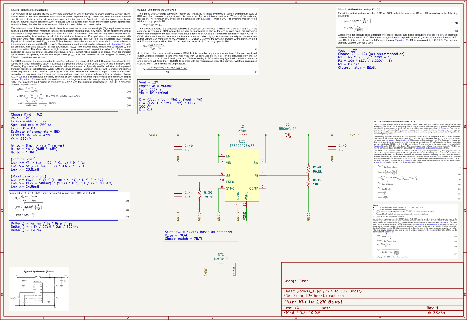
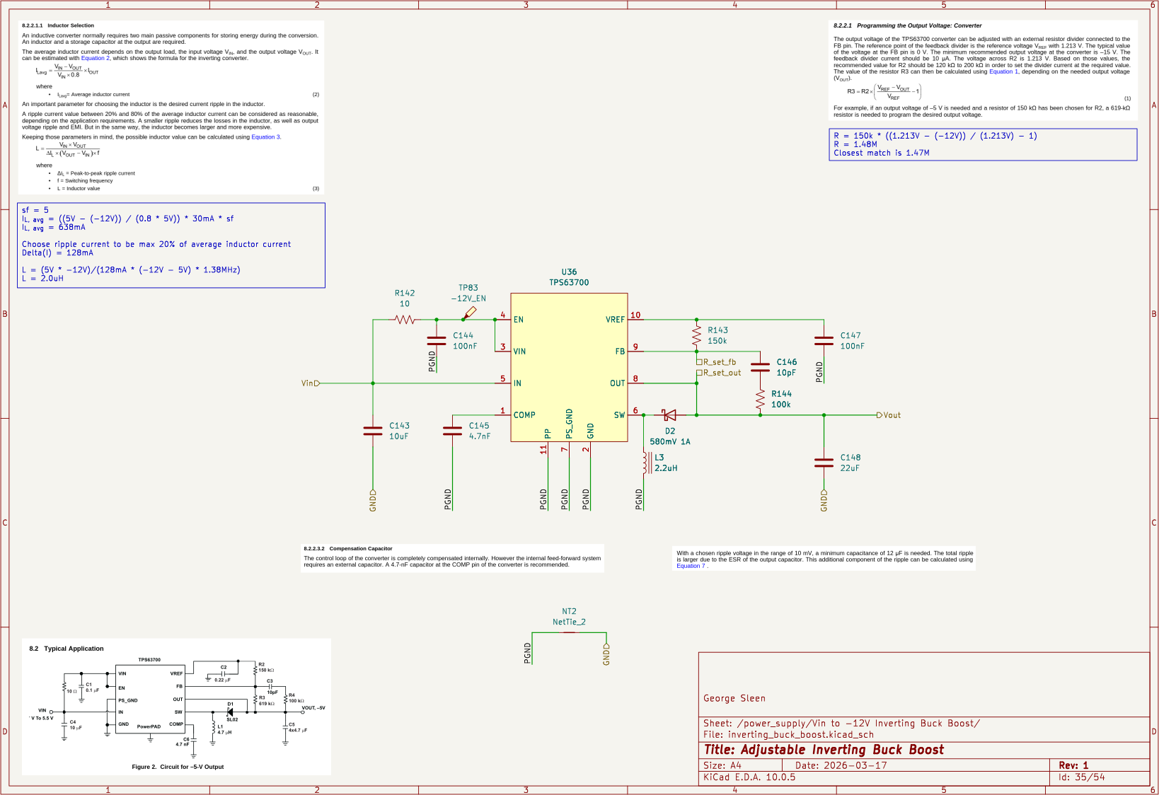
For each converter I worked through the chip's datasheet design procedure and wrote my calculations on the schematic next to the datasheet sections I used, so anyone checking a part value can see where it came from. The first version had:
- A 12 V boost converter for the transmitter
- A -12 V inverting converter, followed by a linear regulator down to -10 V for the ADCs
- A 2.75 V linear regulator for the microphones
After the switch to digital microphones, the negative supplies and the 2.75 V regulator weren't needed anymore and were removed. The 12 V boost and the input mux are still in the current design, along with a 3.3 V converter Josh added for the digital side and the microphones.
12 V boost converter
Transmit
I started the transmit side on an H-bridge driver running from the 12 V rail. An H-bridge can flip which side of the transducer is driven high, so the transducer sees a 24 V swing from a 12 V supply. Josh has since finished wiring it up and added the connector for the transducer.
Tooling
We started with separate repos for the main board, a single-channel dev board, and our part library. I merged them into one repo so everything shares one library and one history, and wrote a setup script that adds the library to KiCad, so either of us can open the boards on a new machine without broken part links.
Challenges
- I couldn't trust my math for the first version of the -12 V supply
- Solution: I had started with a regular buck converter chip wired up to make a negative voltage. The datasheet's design equations assumed the converter would run in continuous mode, but at our 30 mA load it would be running in discontinuous mode, so they didn't really apply. I switched to the TPS63700, a converter made for negative outputs with a design procedure for exactly this, and redid the calculations from its datasheet.
-12 V inverting converter
Repositories
- Hardware: github.com/fizzy-sonar/sonar-hardware